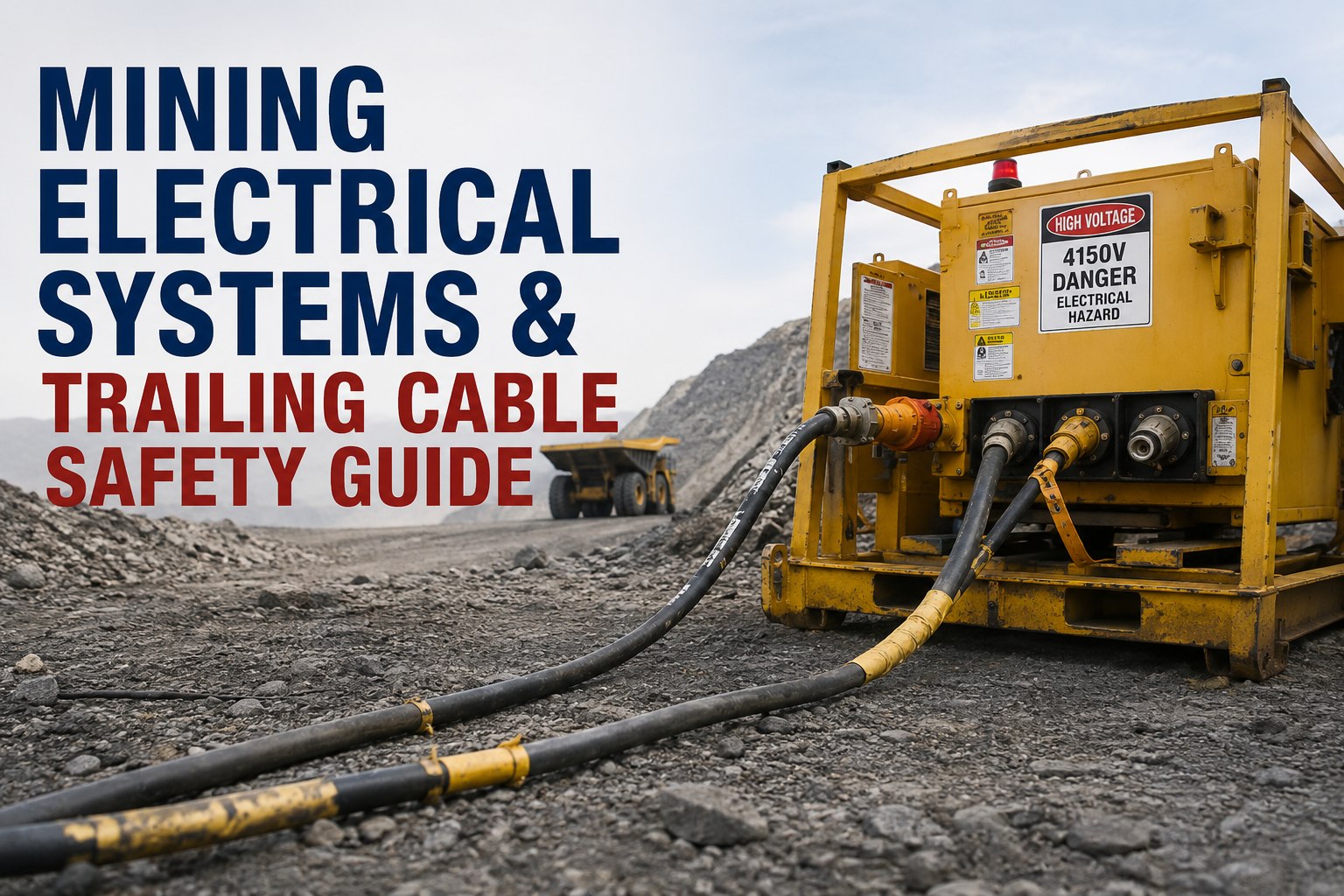
A mining trailing cable carries between 415V and 22kV to an electric shovel, dragline, drill, or pump — energy levels where a damaged outer sheath is a shift-ending safety event. Trailing cable safety is a discipline of consistent visual inspection, documented defects, disciplined isolation before hands-on work, and never trusting ground-fault protection to substitute for either. This guide walks the anatomy, damage patterns, inspection zones, isolation principles, and the documentation workflow that keeps defects from becoming incidents. Book a demo to see cable templates in HVI.
What's Inside a Trailing Cable — and Where It Fails
The outer sheath is the last line of defense. Every layer beneath it is energy that will find a path if the sheath fails.
The outer sheath is the surface you inspect. Everything hazardous lives beneath it. That's why cable inspection discipline focuses entirely on what's visible on the sheath — because any breach of the sheath is a warning that the insulation, the conductors, or the ground path may already be compromised. A qualified electrical worker's assessment is what determines whether a cable stays in service; the documentation and workflow around that assessment is where a good CMMS earns its cost.
The 5 visible defects every cable inspection must documentWhat the operator or inspector looks for on the surface — the qualified electrical assessment happens after
Visual inspection is not a substitute for electrical testing, insulation resistance measurement, or ground-continuity verification — those are electrical technician activities on de-energized equipment following your site's isolation procedure. What follows are the visible surface defects that trigger the electrical assessment. Book a demo to see how visible cable defects flow into a work order and hold the asset for electrical review
Outer sheath damage
What to look for: Cuts, gouges, abrasion patches, chafing wear, thermal damage (hardening, melting, discoloration), rodent damage, mechanical crushing (flat spots or oval cross-section).
Trigger: Any breach of sheath integrity — report immediately, hold for qualified assessment.
Exposed conductors or insulation
What to look for: Any visible inner insulation showing through the sheath, exposed copper, visible ground wire strands, or exposed pilot wire.
Trigger: Immediate out-of-service under most jurisdictions — damaged cable exposing conductors must be repaired or removed from service (see e.g. Virginia Code § 45.2-813(F) for underground coal).
Splice condition
What to look for: Cracks in splice compound, moisture ingress, discoloration around splice, sheath separation at splice ends, splice heating (visible thermal marks).
Trigger: Any splice degradation — log with photo, refer to electrical for assessment against the original splice specification.
Connectors & plugs
What to look for: Cracked shell, arc marks on pins, moisture inside connector body, latch damage, bent or missing pins, evidence of water pooling around a disconnected plug.
Trigger: Any connector damage or moisture exposure — plug incidents (short circuit, disintegration) are documented cable-related failures in mining safety literature. Log and isolate.
Routing & support
What to look for: Cable dragging on sharp ground, tight bend radius (below OEM spec), cable pinched under structures, unsupported spans, exposure to falling material zones, positioning under drop paths of buckets or booms.
Trigger: Not a cable defect per se, but a defect in the operating environment — log as a route correction work order before the environment damages the cable.
Common causes of trailing-cable damageThe mechanisms behind almost every incident in the industry
Understanding damage causes is what turns pre-shift inspection from a "did we look at it" activity into a "did we look at where damage actually happens" activity. Regulatory bulletins from mining safety agencies consistently identify a small number of recurring mechanisms.
Vehicle or equipment contact
Dozers, graders, cable tractors, trucks with raised bodies, light vehicles — any machine that drives over, crosses under, or works near a cable can damage it. A tracked vehicle catching a cable loop is one of the most common documented mechanisms.
Dragging & excessive tension
Pulling too much cable in one drag, snagging on rocks or structural obstacles, exceeding cable tensile spec during shovel walks. Excessive tension separates conductors internally even when the sheath still looks intact.
Sharp ground conditions
Rocky spoil, sharp aggregate, broken concrete around benches, drilled holes, freeze-thaw ground displacement. Cables routed across these surfaces accumulate abrasion wear and puncture damage over time.
Falling material & drop zones
Rocks dislodged by drag chains, material falling from swinging buckets, rocks from spoil piles rolling down onto bench cables. Cable placement below any active bucket swing radius is a recurring incident pattern.
Environmental / weather exposure
Plugs left disconnected in ground depressions filling with rainwater, extreme temperature cycling degrading insulation, UV damage, oil/chemical contact eroding sheath compounds. A pooled plug + rainstorm is a documented incident type.
Poor routing & management
Tight bends below minimum radius, unsupported spans between saddles, cable resting on hot exhaust surfaces, routing that requires cable to be moved on every equipment walk. Bad routing is preventable damage.
Almost every documented cable damage incident maps to one of the six mechanisms above. Pre-shift inspection focused specifically on the terrain, routing, and equipment interactions in the operating area catches more damage than sheath-only inspection ever will. Book a demo to see how routing-and-terrain items get built into a cable pre-shift template
Ground-fault protection: essential, not sufficientWhy protective systems don't replace inspection
Every mining trailing cable installation includes ground-fault (earth-leakage) protection, ground-continuity monitoring, and typically a pilot wire circuit that trips power on cable breakage or plug separation. These protections are essential — they exist because cable failures at these voltages are catastrophic and reaction speed matters. But they are not a substitute for visual inspection, defect documentation, and disciplined isolation. Protection responds after a fault exists. Inspection prevents the fault from developing.
Ground-fault / earth-leakage protection
Detects unintended current flow to ground and trips supply. Sensitivity, response time, and reset behavior configured per installation. Assumes the ground path itself is intact — which is why ground conductor integrity is inspected separately.
Pilot wire circuit
Trips power on cable breakage or plug separation, and prevents energization if pilot circuit is broken. Requires the pilot wire itself to be intact and correctly connected — a compromised pilot wire disables the very protection meant to catch cable damage.
Ground-continuity monitoring
Verifies the ground conductor from the machine frame back to the source ground is continuous. Trips power on ground path loss. Depends on functional test cycles — grounded-phase detection tests are required at shift start per 30 CFR 75.803-1 on HV continuous mining machines.
Visual inspection & documentation
Every shift, before energization. This is the layer that prevents the fault the other three layers would only detect after it happens. Under 30 CFR Part 75 subpart I, a person designated by the mine operator must de-energize and visually inspect the high-voltage trailing cable at the beginning of each shift the machine is energized.
Which is why every serious mining safe work program treats visual inspection findings with the same urgency as protection-system trips — because a documented visible defect on Tuesday is what prevents the protection-system trip on Wednesday. Book a demo to see how inspection findings tie to work orders and repair history in HVI
Isolation & lockout/tagout before any hands-on workGeneral principles — your site procedure is the authoritative document
Any hands-on work on a trailing cable, connector, splice, or the equipment it powers must occur only after full electrical isolation and lockout/tagout by qualified personnel following the site's electrical safe work procedure. What follows is the general principle sequence; the site-specific procedure defines the exact who, what, and how for your operation. Start a free trial to document the completion of these steps on an inspection record — HVI captures the documentation, the site procedure remains the authority.
Notify affected parties & identify all energy sources
Communicate to operators, supervisors, and any downstream affected work. Identify every power source that could re-energize the equipment or cable being worked on.
De-energize at the source
Open the supply breaker or disconnect at the substation, switch house, or distribution point. Physical isolation from the energy source is the primary control — not a downstream stop button.
Apply locks & tags per site LOTO procedure
Each person working on the system applies their own lock. Tags identify who applied the lock, the date/time, and the scope of work. Group LOTO procedures for multi-worker jobs follow the site's specific sequence.
Test for absence of voltage before contact
Use a rated voltage tester on all conductors, verified against a known live source before and after the test. Assumption of dead is not verification of dead. Zero-energy state confirmed before any hands-on work begins.
Perform work — qualified electrical personnel only
Cable splicing, connector rebuilds, insulation repair, ground path restoration — all electrical trade work performed by certified electrical personnel to the applicable standard (e.g., AS/NZS 1747 for reeling/trailing cable repair and testing in Australia, or equivalent in your jurisdiction).
Verify repair & test before removing locks
Post-repair electrical testing per the applicable standard — insulation resistance, ground continuity, high-voltage test where specified. Locks and tags remain in place until testing confirms the system is safe to re-energize.
Remove locks in reverse order, re-energize, verify normal operation
Each worker removes their own lock. Re-energize per the site's controlled restart procedure. Verify normal operating parameters before the equipment returns to production.
From a mine electrical supervisor after a near-miss on an EX3600 shovel cable
Our operator flagged sheath damage on a 7.2kV shovel cable during pre-shift. Small cut, maybe two inches long, no visible inner insulation. Under the old paper system, that would have gotten a hand-written note that maybe made it to the electrical shop by end of shift.
On the digital pre-shift, the operator photographed it, tagged it as a P1 electrical defect, and it fired a work order to the electrical super immediately. He walked out, isolated the cable per our LOTO procedure, and did a proper test. Insulation resistance had already dropped — that "small cut" was compromising the phase insulation underneath. If we'd run another shift on it, we could have had a phase-to-ground fault under load. The documentation chain from operator finding to isolated inspection to work order to repair to test-and-return was one continuous record. That's the value of the paper trail when something goes right.
Frequently asked questions
How often do mining trailing cables need to be inspected?
Frequency depends on jurisdiction, cable voltage class, and equipment type. Under US federal rules for underground coal HV continuous mining machines, 30 CFR Part 75 subpart I requires that at the beginning of each shift the machine is energized, a designated person must de-energize and visually inspect the high-voltage trailing cable for damage to the outer jacket. For surface metal and nonmetal mining, the general MSHA requirement under 30 CFR 56.12028 and 56.12030 is that continuity and resistance of grounding systems be tested at intervals not exceeding 12 months, and defects in electric equipment must be corrected before the equipment is used. Many operators go well beyond minimum requirements — pre-shift visual inspection on every energized cable, weekly documented walkthrough of routing and support, quarterly qualified-personnel assessment. Site electrical safe work procedures define the specific frequency and scope for your operation.
What voltages do mining trailing cables typically carry?
Trailing cables in surface mining commonly carry between 415V and 22kV depending on the equipment they supply and the site's distribution voltage. Small mobile pumps and lighting plants may run at 415V or 600V. Electric drills and smaller shovels typically run at 4.16kV or 7.2kV. Large electric rope shovels, draglines, and primary distribution to major equipment can run at 13.8kV, 15kV, or up to 22kV. Underground coal operations use HV cables typically up to 25kV under 30 CFR Part 75 rules. The voltage class matters for inspection because higher voltages have larger insulation systems, longer minimum bend radii, more stringent splice requirements, and more consequential failure modes — a sheath breach on a 22kV cable is a fundamentally different urgency than the same defect on a 415V cable. Every cable in your inventory should have its voltage class documented on the asset record so responders know what they're dealing with immediately.
Can HVI verify that a cable is electrically safe to return to service?
No. HVI does not perform electrical testing, does not verify insulation resistance, does not confirm ground continuity, does not authorize personnel to work on energized equipment, and does not control electrical isolation. Electrical certification and verification of safe-to-energize status are activities that must be performed by qualified electrical personnel using calibrated test equipment per the applicable standards (e.g., AS/NZS 1747 for cable repair and testing, or the equivalent standard in your jurisdiction). What HVI does is document the workflow around those activities: the pre-shift inspection record with photo evidence of visible defects, the work order created from the finding, the maintenance history of the cable across its lifecycle, and the closeout record when the qualified person signs off. The electrical work stays with electrical personnel. The documentation chain lives in HVI.
Does ground-fault protection make cable inspection less critical?
No — protection systems and inspection discipline serve different purposes and neither replaces the other. Ground-fault (earth-leakage) protection detects unintended current flow to ground and trips supply, typically within a fraction of a second. That's essential — it prevents an active fault from becoming a sustained arc or a shock event. But it responds after the fault exists. Cable inspection prevents damage from developing into a fault in the first place, catches degradation that hasn't yet reached the fault threshold, and identifies environmental or handling issues before they cause the damage. A cable with progressive sheath abrasion may pass every ground-fault test right up until the moment it doesn't — and at that moment, the fault has already occurred. Protection is the safety net. Inspection prevents you from needing the safety net. Both are required by regulation and by any credible site safe work procedure.
What's the safest way to reposition a trailing cable during equipment walks?
Follow the site's cable handling procedure — the specific method depends on the equipment, cable weight, terrain, and available cable handling equipment (cable saddles, buns with slings, purpose-built cable tractors). General principles that apply across most sites: never handle an energized cable manually — isolate first per LOTO procedure if hands-on repositioning is required; use purpose-built cable handling equipment rather than improvised methods (dozer blades pushing cables, chains rigged to trucks); route cables to avoid tight bends, sharp ground, and drop zones under active bucket paths; use physical protection (cable crossovers, elevated supports) where vehicle traffic crosses cable routes; and never drive over a cable without a rated crossover in place. Improvised handling is the mechanism behind a large share of documented cable damage incidents in surface mining safety literature. Purpose-built equipment plus procedure discipline is what keeps cable handling from becoming the incident source itself.
Make cable inspection findings defensible from operator to close-out
HVI supports digital cable inspection checklists, asset-level inspection records with photo evidence, defect documentation with severity flags, maintenance work orders auto-linked to source inspections, and full maintenance history for every trailing cable in the fleet. Actual electrical work, isolation, LOTO, testing, and certification remain with your qualified electrical personnel and site procedures — HVI captures the documentation chain that surrounds them.
No credit card · No hardware · Cable inspection templates ready on day one