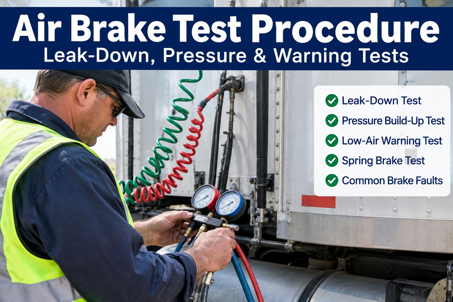
Air brake test procedure is 7 sequential steps, each with a measurable pass/fail threshold: governor cut-out at 120-140 psi, static leak-down under 2-3 psi/min, applied leak-down under 3-4 psi/min, low-air warning at or before 60 psi per 49 CFR 393.52, spring brake pop-out at 20-45 psi, parking hold, and service brake response. Miss any threshold and the truck fails inspection or loses air on the road. This guide walks the 7-step procedure with the exact numbers — book a demo to capture air brake test results per unit in HVI.
The 7-Step Air Brake Test — With the Exact Numbers
Every step has a target, a pass threshold, and a fail signal. Skip the sequence and the test is invalid; skip the numbers and the fault gets through.
Governor cut-out & cut-in
Static (pump-down) leak-down test
Applied leak-down test
Low-air warning device
Spring brake pop-out
Parking brake hold test
Service brake response
Steps 2-5 all run engine OFF, key ON. Restarting the engine in the middle of the sequence invalidates the test — a common CDL skills-test failure.
The rest of this page walks each step with the specific vehicle condition and reading, the air brake system components the test isolates (compressor, governor, air dryer, reservoirs, chambers, valves, spring brakes), the tractor protection valve on combinations, and the common faults each step catches. Book a 30-minute demo to see per-unit air brake test capture with pass/fail history in HVI.
Why steps 2-5 run with the engine OFF — and why so many drivers fail here
The single most common CDL skills-test failure on air brakes is restarting the engine between steps 2 and 5. With the engine running, the compressor immediately rebuilds any lost pressure — masking every leak, every warning device fault, every spring brake threshold miss. The AAMVA model skills test explicitly requires engine OFF, key ON, for the entire sequence from the applied leakage test through the spring brake pop-out. State CDL manuals may vary slightly in wording, but the principle is identical everywhere.
| Step | Engine state | Why the state matters |
|---|---|---|
| 1. Governor cut-out / cut-in | Engine ON, fast idle | Compressor must run to reach cut-out; then fan brakes to verify cut-in |
| 2. Static leak-down | Engine OFF, key ON | Any pressure loss shows true system leak rate without compressor masking |
| 3. Applied leak-down | Engine OFF, key ON | Loads the brake chambers & hoses; leaks that only appear under application |
| 4. Low-air warning | Engine OFF, key ON | Warning circuit tested; running engine rebuilds pressure before warning triggers |
| 5. Spring brake pop-out | Engine OFF, key ON | Pressure must drop into 20-45 psi range to trigger valves |
| 6. Parking brake hold | Engine ON, rebuilt pressure | Verifies spring brake mechanical integrity under drivetrain load |
| 7. Service brake response | Engine ON, in motion | Real-world brake response, pull, feel, and stopping action verified |
Other common failures: releasing the parking brake for step 3 is required (otherwise gauges won't show true service brake loss), timing the full 60 seconds is required (cutting the count short invalidates the test), and pushing both yellow parking valve and red trailer supply valve is required on combination vehicles before the applied leakage test. Skip any of these and the test result is invalid regardless of the numbers. Book a demo to run the 7-step test as a structured DVIR with time-stamped measurements in HVI.
Air brake system components — what each test step actually isolates
Each step of the 7-step test isolates a specific set of components. Knowing which component the test loads helps diagnose the fault when a step fails: a leak-down failure with parking brake released points to one set of parts; a leak-down failure with brake applied points to another; a low-air warning failure points to the warning circuit itself.
Air supply side
Compressor, governor, air dryer, wet reservoir, dry reservoir(s), pressure gauges. Step 1 exercises this side; failure means compressor, governor, drive belt, or intake restriction.
Distribution side
Reservoirs, foot valve (treadle), quick-release valves, relay valves, hoses, lines. Step 2 (static leak-down) exercises this side; failure means reservoir leak or line/valve leak.
Application side
Brake chambers, slack adjusters, cam shafts, s-cams (or discs), chamber diaphragms. Step 3 (applied leak-down) exercises this side; failure means chamber diaphragm or line leak.
Safety side
Low-air warning switch/light/buzzer (49 CFR 393.51), spring brake chambers, parking brake valve (yellow), tractor protection valve, trailer supply valve (red). Steps 4-5 exercise this side.
On a combination (tractor-trailer), the tractor protection valve seals the tractor's air supply from the trailer if the trailer breaks away or a major leak develops on the trailer side. Testing the trailer air connection with glad hands properly seated, both dash valves pushed in, and the trailer service line pressurised catches most trailer-side failures before dispatch. Glad-hand leaks are the single most common preventable air loss on combinations. Start a free HVI trial to log tractor and trailer air-brake test measurements per asset.
Common faults each step catches — and the corrective action
A failed step in the 7-step test isn't the diagnosis — it's the pointer to a specific component set that needs investigation. The step number narrows the fault from "somewhere in the air system" to a specific handful of parts and connections.
Governor fault
- Signal: Cut-out below 100 psi or above 140 psi; slow build
- Suspect: Governor, unloader valve, compressor, drive belt
- Action: Governor pressure adjustment or replacement; compressor test
Static leak
- Signal: >2 psi/min single, >3 psi/min combination
- Suspect: Reservoir leak, foot valve, quick-release, line fittings
- Action: Soap-solution leak test to locate specific fitting/valve
Applied leak
- Signal: >3 psi/min single, >4 psi/min combination under brake
- Suspect: Brake chamber diaphragm, chamber line, treadle valve
- Action: Chamber inspection, diaphragm replacement, line inspection
Warning fault
- Signal: No warning at 60 psi; light or buzzer inoperative
- Suspect: Low-air switch, warning lamp, buzzer, wiring, ground
- Action: Circuit test; switch and lamp/buzzer replacement per 49 CFR 393.51
Spring brake fault
- Signal: No pop-out above 20 psi; valves stuck
- Suspect: Parking valve, trailer supply valve, spring brake priority valve
- Action: Valve service or replacement; verify manufacturer pop-out spec
Hold test fault
- Signal: Vehicle moves under gentle forward pull with parking applied
- Suspect: Spring brake mechanical wear, cracked spring, worn linings
- Action: Brake inspection at rear axles; linings measurement & replacement
Service response fault
- Signal: Pull to one side, delayed response, unusual feel
- Suspect: Slack adjuster out of adjustment, uneven chamber pressure, contamination
- Action: Slack adjuster check per 49 CFR 393.47, chamber pressure balance test
Moisture & freeze
- Signal: Winter-only faults; water discharge from petcocks
- Suspect: Failed air dryer desiccant, tanks not drained
- Action: Daily tank drain; air dryer service per manufacturer
Slack adjuster out-of-adjustment (49 CFR 393.47) is the single most cited air brake violation on CVSA Level I inspections. Automatic slack adjusters that don't self-adjust properly — often from lack of lubrication or excessive heat cycling — produce out-of-adjustment findings that place the truck OOS on the roadside. Manual verification of pushrod stroke length at PM catches this before the roadside inspector does. Book a demo to see slack adjuster measurements captured per wheel end in HVI.
A fleet trainer on the CDL failure that revealed a real fleet-wide fault
I train new CDL drivers at a mid-size regional. We had one new driver fail his skills test on the low-air warning — the warning didn't activate until 52 psi on the yard truck he was using. Examiner failed him, we brought the truck back to the shop assuming it was a warning-switch issue on that one truck. Replaced the switch, sent driver back, he passed easily.
Six weeks later the same thing happened on a different yard truck. Investigated: same failure pattern — warning activating well below the 60 psi threshold. Ran the 7-step check on every truck in our yard training pool: 4 out of 11 had warning activation between 45-55 psi, all with low-air switches installed 2019-2020 by the same aftermarket parts supplier. The switches were spec'd wrong — a supplier had substituted a lower-threshold part.
Corrective action: replaced all 4 switches with OEM-spec parts. But the point isn't the parts — it's that a single CDL skills-test failure exposed a fleet-wide safety compliance defect that would have shown up eventually as a roadside OOS. The 7-step measurements are the safety-net that catches drift the visual inspection never does.
Frequently asked questions
What is the 7-step air brake test?
The 7-step air brake test is the standard CDL skills-test procedure used to verify commercial vehicle air brake systems, based on the 2026 FMCSA model CDL manual and the AAMVA model skills test. Step 1: build pressure to governor cut-out with engine running (typically 120-140 psi cut-out, cut-in around 100 psi). Step 2: static (pump-down) leak-down test with engine off, key on, wheels chocked, parking brake released, wait for initial drop, time 60 seconds — max 2 psi/min for single vehicle, 3 psi/min for combination. Step 3: applied leak-down test with engine off, fully apply service brake, hold 60 seconds after initial drop — max 3 psi/min single, 4 psi/min combination. Step 4: low-air warning device test by fanning service brake to reduce pressure — warning must activate at or before 60 psi per 49 CFR 393.52. Step 5: continue fanning until spring brake valves (parking brake yellow, trailer air supply red) pop out at 20-45 psi. Step 6: parking brake hold test with engine restarted, low gear, gentle forward — vehicle must not move. Step 7: service brake response at approximately 5 mph, apply firmly, no pull, no delay. Steps 2-5 all require engine off; restarting between them invalidates the test.
What are the allowable air brake leak-down rates?
Two separate leak-down tests apply, each with different thresholds by vehicle configuration. Static (pump-down) leak-down test conditions: engine off, key on, wheels chocked, parking brake released, service brake NOT applied, wait for initial pressure drop to stabilise, then time 60 seconds. Maximum acceptable loss: 2 psi/min for a single vehicle (straight truck or bus), 3 psi/min for a combination vehicle (tractor-trailer). Applied leak-down test conditions: engine off, key on, wheels chocked, parking brake released, service brake fully applied and held for 60 seconds after initial drop stabilises. Maximum acceptable loss: 3 psi/min for a single vehicle, 4 psi/min for a combination. Vehicle configuration matters because a combination has more chambers, more lines, and more fittings — so the acceptable loss is proportionally higher. Common test errors: starting the timing before the initial drop stabilises (produces false failure), releasing the service brake mid-test on the applied test (invalidates), restarting the engine to rebuild pressure (invalidates), leaving the parking brake set during the applied test (gauges won't show true service brake loss), not pushing both yellow parking valve and red trailer supply valve on a combination before the applied leakage test. Any of these procedural errors makes the reading invalid regardless of the number.
At what pressure should the low-air warning activate?
The low-air warning device must activate at or before 60 psi per 49 CFR 393.52. Both a warning light and a buzzer are typically required, and both must be functional. The purpose is to give the driver clear notice that air pressure is dropping toward the spring brake activation threshold (20-45 psi) so they can safely bring the vehicle to a controlled stop before the spring brakes engage automatically. If the warning does not activate until below 60 psi, the driver may lose air pressure without knowing until the spring brakes engage suddenly — potentially at highway speed with catastrophic results. Test procedure: with engine off, key on, wheels chocked, fully release parking brake, then fan the service brake pedal to bleed down pressure while watching the gauge. The warning light and/or buzzer must activate at 60 psi or higher on the gauge. Continue fanning to verify the spring brake valves (yellow parking brake, red trailer air supply on combination) pop out between 20 and 45 psi. Common failure modes: burned-out warning bulb (visual only), disconnected buzzer wire, corroded low-air switch, aftermarket switch spec'd at wrong pressure threshold. Any warning failure at inspection is a citable defect under 49 CFR 393.51 and can trigger a full Level I inspection.
Why must the engine remain off for parts of the air brake test?
Steps 2 through 5 of the 7-step air brake test (static leak-down, applied leak-down, low-air warning, spring brake pop-out) all require the engine off with the key on. The reason: with the engine running, the compressor immediately rebuilds any lost pressure — masking every leak, every warning device fault, every spring brake threshold miss. The compressor loads and unloads based on system pressure and can maintain the reservoirs at governor cut-out indefinitely, so a running-engine leak-down test simply won't show any loss regardless of how bad the system leaks are. Similarly, running the engine will prevent the pressure from dropping into the ranges where the low-air warning (at 60 psi) and spring brake valves (at 20-45 psi) actually activate — making it impossible to verify those safety devices. Correct sequence: build pressure to governor cut-out with engine on (Step 1), then shut the engine off but leave the key in the on position for gauges and warning devices, chock the wheels, and work through Steps 2-5 without restarting. Restart the engine only for Step 6 (parking brake hold test, which needs drivetrain force to verify the spring brake mechanically holds) and Step 7 (service brake response in motion). Restarting the engine anywhere in Steps 2-5 invalidates that step and requires starting over — a common CDL skills-test failure that also produces incorrect fleet inspection results.
Should driver pre-trip air brake tests be treated the same as formal DOT inspections?
No — they serve related but distinct purposes and different regulatory frameworks apply. Driver pre-trip air brake tests under 49 CFR 396.13 (and the AAMVA model skills test procedure) are the daily driver responsibility: verify the system is safe to operate at the start of each duty period, catch obvious defects before dispatch, and document results in the DVIR. The 7-step CDL procedure covered in this article is the standard structure for these driver-side tests. Formal DOT inspections under 49 CFR 396.17 (annual periodic inspection) and CVSA Level I roadside inspections apply more rigorous procedures including pushrod stroke measurement per 49 CFR 393.47 for brake adjustment, chamber size verification against the applicable stroke chart, and inspector-side torque and leak testing that go beyond driver pre-trip capability. Numerical limits and pass/fail thresholds in both frameworks change periodically, and state-specific inspection programmes may impose additional or different requirements on top of the federal minimums. Always confirm current FMCSA regulations, current CVSA out-of-service criteria (updated annually), and applicable state inspection requirements before using specific numerical limits operationally — the numbers in this article reflect the 2026 FMCSA model CDL manual and are correct at time of writing, but rely on the current published sources for the version in effect on the day of any inspection.
Turn the 7-step check into 7 time-stamped measurements per unit per trip.
HVI runs air brake pre-trip DVIRs as structured numeric measurements: governor cut-out psi, static and applied leak-down rates, warning activation psi, spring brake pop-out psi, plus pass/fail for parking brake hold and service response. Every reading captured per unit with time-stamp and photo evidence on defects. Recurring failures per truck surface as pattern signals. Confirmed defects route into corrective work orders. Slack adjuster stroke captured per wheel end at PM. Live in under two weeks. No hardware. No credit card.
Trusted by fleets running structured air brake compliance across USA, Canada, UK & Australia · Ready on day one