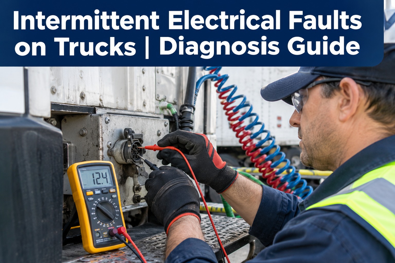
Intermittent electrical faults on trucks and trailers are the ones that vanish the moment the technician plugs in a scan tool. Lights flicker on the highway then work in the bay. A trailer disconnect alarm fires at 55 mph then clears at idle. Every fault has a trigger — vibration, moisture, heat, cold, or load state — and identifying the trigger identifies the location. This guide walks the 5-trigger matrix and the diagnostic tests visual inspection misses — book a demo to track repeat electrical faults per asset in HVI.
Intermittent Electrical Faults — The Trigger Tells You Where
Every intermittent fault has a trigger. Rain, road vibration, cold morning, hot afternoon, engine load. Match the trigger to the fault fingerprint — and the location narrows from "somewhere in the harness" to a specific 6-inch section.
Get the driver to describe when the fault happens — not just what happens. The when is where the diagnosis actually starts.
The rest of this page walks the 7-way trailer connector (single biggest source of trailer electrical faults), ground straps and why bad grounds create apparently unrelated failures, voltage drop testing that reveals what continuity tests miss, the difference between fixing a component and proving the circuit, and repeat-failure tracking per asset. Book a 30-minute demo to see per-asset electrical fault history in HVI.
The 7-way trailer connector — where most trailer electrical faults live
The 7-way SAE J560 blade connector between tractor and trailer carries seven circuits (ground, taillights, left turn/brake, right turn/brake, auxiliary, electric brakes, 12V charge) and it lives outside — exposed to road salt, water, dirt, and mechanical stress every mile the trailer moves. Industry sources estimate that ground loops and voltage drop through this connector cause roughly 80% of all trailer lighting failures, and the failure patterns are consistent enough that the diagnostic sequence is worth memorising.
Visual first
Uncouple. Inspect both plug and socket. Look for green/white corrosion powder on pins, bent or spread female contacts, damaged rubber boot allowing moisture, obvious burn marks or discolouration on any pin. Corrosion visible = fault confirmed.
Test with known-good trailer
Before replacing anything, swap in a known-good trailer or use a 7-way circuit tester at the truck connector. This isolates the fault to truck side or trailer side. Skipping this step is how fleets replace $200 of parts trying to fix a fault that was on the other unit.
Pin-by-pin voltage check
With test load on trailer side, measure voltage at each pin at the connector face vs the same circuit at battery. Voltage drop >0.5V on any pin under load indicates high resistance at that pin, connector, or the wire between. Ground pin (white) failures produce the most confusing symptoms.
Clean, protect, retest
Clean corroded pins with electrical contact cleaner and a small wire brush. Straighten spread female contacts (or replace socket if severely spread). Apply dielectric grease to all pins before reconnecting. Retest under load to confirm voltage drop back within spec (<0.2V per pin).
Recent OEM recalls confirm the pattern. Ford recall 26V-104 covers 2021-2026 F-Series with trailer module software faults; Ram recall 26V-059 covers 2025-2026 HD trucks with Trailer Tow Module issues that can cause loss of trailer lights and brakes. But even on unrecalled fleets, the vast majority of "trailer disconnect" alarms trace to corroded 7-way pins or a bad ground — not to a failed module. Always test before replacing. Book a demo to see 7-way connector inspection templates with photo evidence in HVI.
Grounds — why a bad ground creates apparently unrelated faults
A ground fault produces the most confusing symptom pattern in electrical diagnosis because the same ground point serves multiple circuits. When it fails, current from one circuit backfeeds through another looking for a path to negative, producing "impossible" symptoms: headlights dim when the turn signal blinks, the reefer temp display resets when the tractor brakes, dash gauges flutter when the ABS activates. These are ground faults masquerading as component failures.
| Ground location | Circuits it serves | Symptom when it fails |
|---|---|---|
| Battery to frame strap | Primary ground for entire truck | Cranking sag, module resets, dim lights across the board |
| Engine to frame strap | ECM, sensors, injector returns | Sensor codes, misfire, hard start, computer resets under load |
| Cab to frame strap | Cab lighting, dash, HVAC, radio | Dashboard flicker, HVAC fan cycling, dome light behaviour changes |
| Body to frame strap | Marker lights, rear lights, trailer feed | Trailer lights flicker with cab loads, tail light brightness inconsistent |
| Trailer harness ground | All trailer circuits including brakes | Cross-lit signals, brake controller faults, hyper-flash on turns |
| ABS module ground | ABS controller, wheel-speed sensors | Intermittent ABS codes, sensor faults across multiple wheels |
| Reefer ground (if trailer) | Reefer controller, alarms, telematics | Setpoint resets, false alarms, telematics dropouts |
Ground inspection method: every ground strap gets visually checked (green/white corrosion, cracked lug, loose bolt), physically wiggled (any movement = suspect), and voltage-drop tested under load. The most common fault is a ground strap that looks perfect visually but has 0.8V drop under load because corrosion has developed between the lug and the mating surface. Torque check the strap fasteners at annual PM — loose ground bolts back off from vibration over 6-18 months. Book a demo to see ground strap inspection templates per asset in HVI.
Voltage drop testing — the test that catches what continuity misses
A continuity test on a wire with 80% of its copper conductors corroded through will show "good" — the remaining 20% of copper conducts fine at the millisecond current a multimeter continuity mode uses. Under real load (10-30 amps for lights, 40-100 amps for a starter), the same wire drops voltage because the 20% of intact copper can't carry the current without resistance heating. Voltage drop testing loads the circuit,and measures the loss under working conditions.
Setup
- DVOM on 2V DC range
- Circuit powered & loaded normally
- All connections seated
- Battery fully charged before testing
- Full load applied to circuit
- Ambient temp noted (affects readings)
Positive-side drop
- Red probe on battery +
- Black probe on load side (at component)
- Reading = drop across positive feed
- Target: <0.2V for lighting circuits
- Investigate: 0.2-0.5V
- Failing: >0.5V per side
Ground-side drop
- Red probe on component ground return
- Black probe on battery negative
- Reading = drop across ground path
- Same thresholds as positive
- Ground drops more common than positive
- Chassis paint under lug = classic cause
Isolate the fault
- If drop is high, walk the circuit
- Test across each connection point
- Highest single drop = fault location
- Clean or replace that connection
- Retest to confirm <0.2V after fix
- Document baseline for next inspection
The advantage of voltage drop over continuity: catches the developing fault before it becomes a hard failure. A connection with 0.3V drop under load today will be 0.6V drop next quarter and an open circuit within a year. Catching the connection at 0.3V costs a five-minute cleaning; catching it at open-circuit costs a roadside service call plus a trailer full of stranded cargo. The tool is a $30 multimeter. The savings scale with fleet size. Start a free HVI trial to log voltage-drop measurements per circuit per asset.
A fleet technician on chasing an intermittent for six months
We had one Kenworth T680 — truck 3892 — throwing intermittent trailer disconnect alarms and ABS codes across three different trailers over six months. Every time the truck came in, faults cleared, everything tested fine. Replaced two trailer modules on the trucks, two ABS wheel speed sensors on trailers, one bumper harness. None of it fixed anything.
Finally caught the pattern by asking drivers when it happened, not what happened. Every fault report was after rain or morning humidity. Uncoupled the truck and sprayed the 7-way socket with water. Fault reproduced in 30 seconds. Ground pin corrosion under the rubber boot — invisible from outside because the boot looked intact. Boot had a tiny crack on the underside letting moisture in over months. Cleaned the pin, replaced the socket, applied dielectric grease. Zero fault reports in the 14 months since.
Six months of shop time and roughly $1,800 in parts trying to fix it component-by-component. Fixed it in 45 minutes once I asked the right question. The trigger was the diagnosis. The parts weren't.
Frequently asked questions
How do you find an intermittent electrical fault on a truck?
Start with the trigger, not the component. Every intermittent electrical fault has a trigger condition — vibration (fault appears on rough roads or highway speed), moisture (appears after rain, wash, or humid morning), heat (appears after engine reaches operating temp), cold (appears on first cold start, clears when warm), or load state (appears only under high current draw). Ask the driver when the fault happens, not just what happens. The when narrows the location. Vibration-triggered faults point to chafed harness at brackets or engine mounts, cracked solder joints, or loose pins. Moisture-triggered faults point to the 7-way trailer connector, bumper harness, or under-body splices with corroded connections. Heat-triggered faults point to connectors near exhaust or turbo, or thermally-marginal joints. Cold-triggered faults point to aged solder splices or brittle wire insulation that contracts open. Load-state faults point to ground straps, battery cables, or main power feeds with high resistance under load. Once the trigger tells you the location, use targeted tests: wiggle test with meter connected, water spray to reproduce moisture faults, heat gun or freeze spray to reproduce temperature faults, voltage drop testing under load for load-state faults. The trigger IS the diagnosis; the parts you replace are just the last step.
Why do 7-way trailer connectors fail so often?
The 7-way SAE J560 connector carries seven critical circuits (ground, taillights, left turn/brake, right turn/brake, auxiliary, electric brakes, 12V charge) between tractor and trailer, and it lives fully exposed to road salt, water, dirt, and mechanical stress every mile the trailer moves. Industry sources estimate ground loops and voltage drop through this connector cause roughly 80% of all trailer lighting failures. The three most common failure modes: corrosion (green or white powder on pins from moisture and salt, breaking the electrical connection); spread or bent female contacts inside the truck socket (creates loose fit and intermittent connection, produces "Trailer Disconnected" messages on modern trucks); and damaged rubber boot allowing moisture to reach the pin base even when the pin surface looks clean. Manufacturer recalls confirm the pattern: Ford recall 26V-104 covers 2021-2026 F-Series with trailer module software issues that can cause loss of trailer lights and brakes, and Ram recall 26V-059 covers 2025-2026 HD trucks with similar Trailer Tow Module problems. But even on unrecalled fleets, most trailer disconnect alarms trace to corroded 7-way pins or a bad ground — not to a failed module. Always test with a known-good trailer or a 7-way circuit tester before replacing modules. Regular cleaning with electrical contact cleaner, dielectric grease application, and boot condition inspection at every trip prevents most of these failures.
What is a voltage drop test and why does it matter?
A voltage drop test measures the voltage lost across a wire, connector, or ground path while the circuit is under normal load, which no static continuity test can reveal. A continuity test on a wire with 80% of its copper conductors corroded through will show "good" because the remaining 20% of copper conducts fine at the millisecond current a multimeter continuity mode uses — but under real load (10-30 amps for lights, 40-100 amps for a starter), the same wire drops voltage because the 20% of intact copper cannot carry the current without resistance heating. Method: DVOM on 2V DC range, circuit powered and under full load, one probe on battery positive, other probe on load side at the component — the reading is the drop across the positive feed. Repeat with probes on component ground return and battery negative for the ground path. Interpretation: below 0.2V per side is healthy, 0.2-0.5V requires investigation, above 0.5V is a definite fault. Walk the circuit to isolate: test across each individual connection point, and the highest single drop identifies the specific fault location. Clean or replace that connection, then retest to confirm below 0.2V. The advantage over continuity testing: catches developing faults before they become hard failures — a connection at 0.3V drop today becomes 0.6V next quarter and open-circuit within a year.
Can a bad ground cause multiple unrelated electrical problems?
Yes, and this is the single most common source of confusing "unrelated" electrical symptoms on commercial trucks. A ground point serves multiple circuits simultaneously, and when that ground develops resistance or fails, current from one circuit backfeeds through another looking for a path to negative. This produces symptoms that appear impossible: headlights dim when the turn signal blinks, the reefer temperature display resets when the tractor brakes are applied, dashboard gauges flutter when the ABS activates, trailer marker lights flicker in sync with the cab dome light. Each symptom individually looks like a component fault, and technicians who chase them component-by-component replace parts that were never faulty. Common ground locations and their symptom patterns: battery-to-frame strap failure produces cranking sag, module resets, and dim lights across the entire truck; engine-to-frame strap failure produces sensor codes, misfires, and hard starts; cab-to-frame strap failure produces dashboard flicker and HVAC cycling; body-to-frame strap failure produces trailer light flicker synchronised with cab electrical loads; ABS module ground failure produces multiple wheel-sensor codes. Ground inspection method: every ground strap gets visually checked (corrosion, cracked lug, loose bolt), physically wiggled (any movement = suspect), and voltage-drop tested under load. Most commonly, the strap looks perfect visually but has 0.5-0.8V drop under load because corrosion has developed between the lug and the mating surface.
Should you replace a component or prove the circuit first?
Always prove the circuit before replacing a component. The temptation on intermittent faults is to replace the most likely component and see if the fault clears — and on paper this seems faster than running diagnostic tests. In practice it almost always costs more time and money than the systematic approach. A "shotgun" repair strategy on an intermittent fault typically requires 2-4 component replacements before the actual fault is found, each requiring shop time and each producing labour cost. And a component replaced without proving the circuit often gets damaged by the same underlying fault (a new alternator installed on a truck with 0.8V ground drop will fail the same way the old one did within 6-12 months). The correct sequence: first identify the fault trigger via driver report (when does it happen); second use the trigger to narrow location; third run targeted tests (wiggle test for vibration triggers, water spray for moisture triggers, voltage drop under load for load-state triggers); fourth prove the specific circuit fault before ordering parts; fifth clean, repair, or replace the specific connection or component identified; sixth retest under the original trigger condition to confirm the fault does not reproduce. Total time on a proven-circuit repair typically runs 60-120 minutes; total time on a shotgun repair on the same fault typically runs 4-12 shop hours across multiple visits.
Stop chasing intermittent faults. Start recording them.
HVI captures electrical inspection results per asset with structured fields for voltage drop measurements, connector condition, ground continuity, and pin-by-pin test results. Photos attach to every defect. Repeat intermittent faults on the same truck or trailer surface as a pattern signal — not as a fresh mystery each service visit. Confirmed defects route into corrective work orders. The truck that keeps eating parts becomes the truck with a documented root cause fixed once. Live in under two weeks. No hardware. No credit card.
Trusted by fleets running structured electrical diagnostics across USA, Canada, UK & Australia · Ready on day one